Each of the five bands has four wire pieces. Two are connected together and form the reflector, while two are used in the driven element connected from each side of the coax feed. Each wire was cut to length and soldered to a wire ring for attachment to the brass bolts on the mast.
| Driven Element (One side) |
Reflective Element (One side) |
|
|---|---|---|
| 20m | 217.3" |
220.5" |
| 17m | 167.3" |
169.7" |
| 15m | 143.1" |
145.5" |
| 12m | 120.1" (see note) |
122.4" |
| 10m | 107.5" |
109.3" |
These lengths are based on the work done by Holger, DL7IO. He has done a lot of experimental work and modeling on the design.
In the end, I had to add about 2" to the 12m lengths above. The others worked out fine and didn't need tweaking.
For the end spacing, I used the following measurements:
| Driven Element to spreader | Reflective Element to spreader | |
|---|---|---|
| 20m | 6.7" |
4.3" |
| 17m | 5.3" |
3.5" |
| 15m | 4.7" |
3.1" |
| 12m | 4.1" |
2.6" |
| 10m | 3.7" |
2.4" |
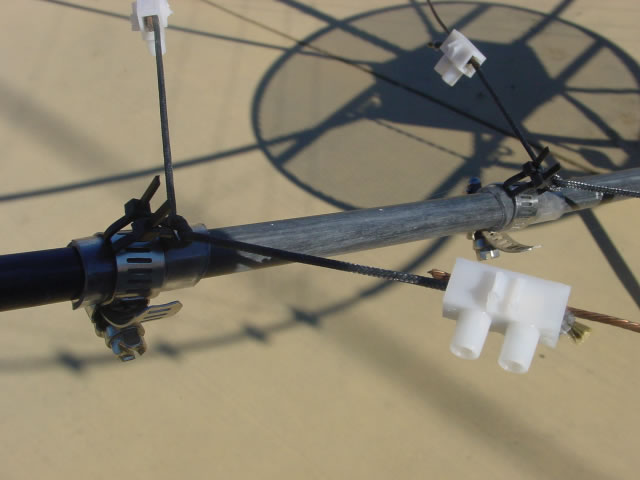
It was easiest to make these adjustments with the end attachments I built. At the spreader, a short (about 1") piece of plastic tubing was pushed over the fiberglass tubing. Around this went a hose clamp with two zip ties through it. The zip ties formed a small loop, which I tied some kevlar line to. The two ends of the kevlar line went out to the terminal blocks that held the wire and line together.
To adjust the end spacing, simply loosen the two screws in the terminal block and slide the wire or cord to the desired position. Then just tighten the screws and it all stays in place.
The terminal blocks were from Radio Shack. I didn't keep the packaging, but I think it's part number 274-679 described as "12-position, Euro-style terminal strip holds 10- to 22-gauge wire and is rated up to 30 amps". Cut them apart with heavy wire clippers or sheet metal shears.
The rope is Kevlar / Dacron mix from RadioWorks.